
Page 16 - hb1713_2
P. 16
R.L.W.
Pioneer Oil Refinery: California Star Oil Works kit #RLW-1680
STORAGE TANKS
The storage tanks currently on the hillside above the stills are reported to not be
from the period of significance. The historic record varies from vague to
contradictory in its description of the crude oil storage tanks on site during the
refinery’s operations. Early accounts state the oil storage tanks capacity at 20
and 100 barrels were on the hillside above the stills; another source states these
were 50 barrel tanks. Probably the tanks were replaced and upgrade more than
once during the active use of the site, either as a refinery in the early years or as
a transfer point from storage from the Pico Canyon oil field output to loading to
tank cars. Additional to the crude oil storage tanks, there was apparently a water
storage tank from which the pump house drew its supply which was pumped the
600 feet up and seven miles to the Pico Canyon field.
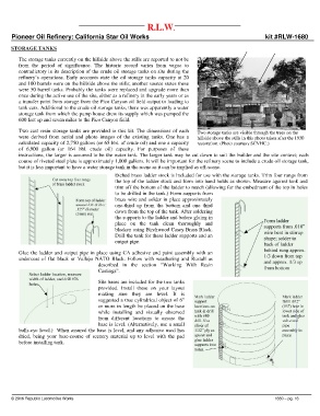
Two cast resin storage tanks are provided in this kit. The dimensions of each Two storage tanks are visible through the trees on the
were derived from aerial and photo images of the existing tanks. One has a hillside above the stills in this photo taken after the 1930
calculated capacity of 2,750 gallons (or 65 bbl. of crude oil) and one a capacity restoration. (Photo courtesy SCVHC.)
of 6,900 gallon (or 164 bbl. crude oil) capacity. For purposes of these
instructions, the larger is assumed to be the water tank. The larger tank may be cut down to suit the builder and the site context; each
course of riveted steel plate is approximately 1,000 gallons. It will be important for the refinery scene to include a crude oil storage tank,
but it is less important to have a water storage tank in the scene as it can be implied as off-scene.
Etched brass ladder stock is included for use with the storage tanks. Trim four rungs from
the top of the ladder stock and form into hand holds as shown. Measure against tank and
trim off the bottom of the ladder to match (allowing for the embedment of the top in holes
to be drilled in the tank.) Form supports from
brass wire and solder in place approximately
one-third up from the bottom and one third
down from the top of the tank. After soldering
the supports to the ladder and before gluing in
place on the tank clean thoroughly and
blacken using Birchwood Casey Brass Black.
Drill the tank for these ladder supports and an
output pipe.
Glue the ladder and output pipe in place using CA adhesive and paint assembly with an
undercoat of flat black or Vallejo NATO Black. Follow with weathering and Rustall as
described in the section “Working With Resin
Castings”.
Site bases are included for the two tanks
provided. Install these on your layout
making sure they are level. It is
suggested a true cylindrical object of 6”
or more in length be placed on the base
while installing and visually observed
from different locations to assure the
base is level. (Alternatively, use a small
bulls-eye level.) When assured the base is level, and any adhesive used has
dried, being your base-course of scenery material up to level with the pad
before installing tank.
© 2016 Republic Locomotive Works 1680 – pg. 16