|
|

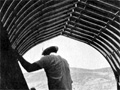
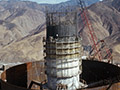
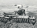
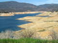
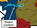
Squadron of Giant Tillers Speed California's Castaic Dam.
Towner Manufacturing Co., P.O. Box 6096, Santa Ana, Calif. 92706.
|
Sales sheet from Towner Manufacturing Co. of Santa Ana, touting its work on the construction of the California Department of Water Resources' Castaic Dam. Undated; latest (only) date mentioned is October 1, 1969. Towner provided the heavy equipment mentioned in this "job report." According to historian Kevin Cabrera of Santa Ana, writing in the Orange County Register (November 20, 2013):
Santa Ana-based Towner Manufacturing Company (1915-1986) specialized in farming equipment and implements. Opened and operated by Fred Towner, a trained and highly skilled blacksmith, the company initially started repairing automobile springs. He quickly gained a reputation for repairing farm implements and switched to developing and manufacturing his own farming equipment. [Later, Towner Road Discers and Scarifiers] were used by the California Highway Commission and by numerous highway departments in other states. The tools were used for mixing and pulverizing macadam, oiled, or gravel roads.
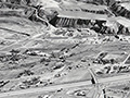
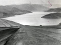
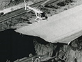
Photos and report by Ray Day, Western editor for Construction Equipment Magazine. Job: Castaic Dam Location: 25 Miles N.W. of Los Angeles Equipment: 3 D9 Tractors with 3 squadron units of 2 ea. 851-144 Towner Wheel Tillers Work Description: Earthen Dam Construction METHODS SPECIFICATIONS, which hold tight control on earthwork accuracy at California's Castaic Dam, haven't slowed contractor production in the least. Western Contracting Corporation is placing up to 125,000 cu yd of earthfill every 17 hr. workday. California Department of Water Resources specs are equally binding on that agency. Castaic Dam sets very close to shifting San Andreas earthquake fault. Only very careful control will do. So, DWR engineers are especially careful with the critical impervious clay center zone. They want to know that lifts are spread for 6 in. compacted thickness, that the soil is thoroughly disc-mixed with an extra 1% of moisture above compaction optimum and that each lift gets 12 sheepsfoot roller passes of specified weight. MIX, MOISTURE, COMPACTION ALL CRITICAL — M.F. Travis, Project Manager for WCC, realized from the start that the key to handling 7350 cy/yd (125,000 cy in 17 hr.) input was a large, capable spread of mixing, watering and compaction equipment. He selected squadron-type multiple disc tillers, made by Towner Mfg. Co. of Santa Ana, Calif., whose mixing performance is designed for 14,000 cy/hr on single pass, 12 in. depth mixing. Diluted by the multiple passes required on this job, it still gave Travis the safe working edge he wanted from this equipment. SHEEPSFOOT ROLLERS — Travis also selected self-propelled sheepsfoot rollers that do their jobs faster than scrapers pour in the material, always staying ahead of the input "market." This "market" for material disposal is vital at Castaic Dam, because only high input will close the dam this construction season and complete the job on time at a profit. Nowhere is this more true than in Zones 1A and 1B. They're the impervious, fine-grained zones in the center of the structure. Built from weathered and unweathered Castaic shales and clays, they form the plastic water tight barriers in the 5200 ft. long, 335 ft. high structure, beyond which point the phreatic line (maximum reservoir water penetration) will permit no further intrusion. THE IMPORTANT MIXING-PULVERIZING JOB on weathered and unweathered shale in Zones 1A and 1B is being handled by three pairs of extra heavy duty Model 851-184 Towner Wheel Tillers. Two squadrons wheel tillers are being used continuously. The third machine fills in at peak effort or serves as a standby. Each machine weighs in at 33,000 lbs., and requires a D9 Cat tractor for peak-performance towing. The squadron tiller cuts a soil swath 24 ft. wide and each unit has thirty-six 3-foot-diameter notched disc blades on tight 14 in. spacing. One unit, the first delivered, uses 38 in. diameter blades on 16¼-in. spacing. Blades are bolted to steel spacer spools and the axles with high-strength bolts. Ball bearing mounting of disc gangs, coupled with double oscillating wheel axles for balance and proper depth control, have proved themselves on the broad, rough impervious fill. As this equipment works, its disc blades cut easily through the loose lift being processed, pitching individual windrows of material through each other. PRODUCTION — Each squadron tiller becomes: (3 MPHx 5280 ft./hr. x 0.5 ft./lift x 24' width = 7000 cu. yd./hr.) / 27 cu. ft. With five to six passes per lift required to completely process the material, the net production is approximately 1000 cy/hr of embankment per unit. To equal this kind of mixing performance on compaction, WCC exercised one option in the specs which permits the use of equipment not designated, if it can give results equal to or better than those named in the specs. A new self -propelled sheepsfoot roller developed by Pactor Co. was brought in on that basis. Biggest compaction unit is a 10 ft. wide self-propelled, double drum machine made by R.G. Le Tourneau. It pulls itself through the impervious zones at 7 mph, and because it's a double drum machine, it requires only six passes. Other rollers are Ferguson sheepsfoot singles, and Pactor 3-wheelers. OTHER EQUIPMENT ON JOB — When these pictures were made, WCC was pouring over 30,000 cu yd a day in the impervious zone alone, to get a closure before fall rains. The "market" idea is paying off in unlimited surface dumping capability on the fill. WCC's Project Manager called on three tested equipment systems to move yardage fast. Rubber-tire motorized scrapers race from borrow pits to fill zones with impervious and marginal materials. In the riverbed, swinging almost lazily with power to spare, a big 191-M Marion dragline loads trucks with a rattle of bridle chain on each dump, excavating riverbed cobbles. And a shovel-truck system, again involving a Marion 191-M, is handling the coarse, heavy cobbles and gravel whose sheer weight will buttress the dam's downstream zone. The scraper fleet includes six Cat 666's, five Cat 657's and sixteen Euclid SS40's. Pushloaded by Cat Quad-9's they excavate prewatered borrow material that's slightly on the dry side and not well pulverized when it reaches Zone 1. As the extra water pours in from water tankers, processing begins immediately. Wabco 65 haulers with modified Athey wagons are hauling from the 191-M shovel and dragline. The material they haul goes into the 28 chimney-drain zone or the Zone 3 previous shell zone. TEST FILL HELPS SELECT EQUIPMENT — DWR engineers actually built a test fill, from local materials to determine the types and sizes of processing equipment the contractor would be required to furnish. DWR engineers then coordinated their studies of the test fill with their own past experience in earth and rock dams. And recommendations made by the U.S. Bureau of Reclamation were considered. FROM THESE EXPERIMENTS AND STUDIES CAME THESE BASIC REQUIREMENTS WHICH NOW GOVERN PROCESSING: 1. Prewetting of borrow areas for impervious zones. 2. Heavy duty disc mixing of impervious zone materials by squadron wheel tillers. Purpose: to break up shale lumps, to mix the various types of materials thoroughly, and to get uniform distribution of the moisture content through the soil, including that added on the fill. 3. Sheepsfoot rolling of plastic soils, with foot-area weight of not less than 4000 lbs. per lin. ft. of drum length. 4. Vibratory compaction for the granular previous zones. CONCLUSION "Ideally," said the DWR engineer in charge of compaction, "we like to get 1% above optimum moisture in the impervious zone before compaction. That gives us a plastic core that won't develop shear planes and settlement the way it would if it was compacted on the dry side. Also, it helps to compensate for evaporative losses." Western Contracting has placed about 18,400,000 cy yd as of October 1, 1969, and has 26,600,000 cu yd remaining. By observing the "market" — input fundamental of high speed earthmoving all the way, Travis expects to furnish Castaic Dam with time to spare.
LW3481: pdf of original document purchased by Leon Worden. Download individual pages here.
|
History of Santa Clarita Water Co./Division
Dissolution of Santa Clarita Water Co.
10-25-2017
Construction Starts 1966
Construction 1967-70 x10
Towner Mfg. Constrution Report 1969
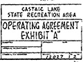
Castaic Lake: 50-Year Operating Agreement 1969
Aerial 12/5/1970
Boat Launch 1972
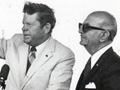
Dorn at Afterbay Opening 5/22/1972
Dorn-Haddad 5/22/1972
Main Lake Opens 6/26/1972
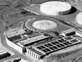
CLWA Facility 1980
"Dinocroc" 2004
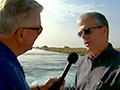
Huell Howser:
Groundwater Banking 2008
Drought 2015
Recycled Water Main Extension, Central Park, 12/13/2017
Aqueduct Ruptures in AV, 1971
|


The site owner makes no assertions as to ownership of any original copyrights to digitized images. However, these images are intended for Personal or Research use only. Any other kind of use, including but not limited to commercial or scholarly publication in any medium or format, public exhibition, or use online or in a web site, may be subject to additional restrictions including but not limited to the copyrights held by parties other than the site owner. USERS ARE SOLELY RESPONSIBLE for determining the existence of such rights and for obtaining any permissions and/or paying associated fees necessary for the proposed use.
